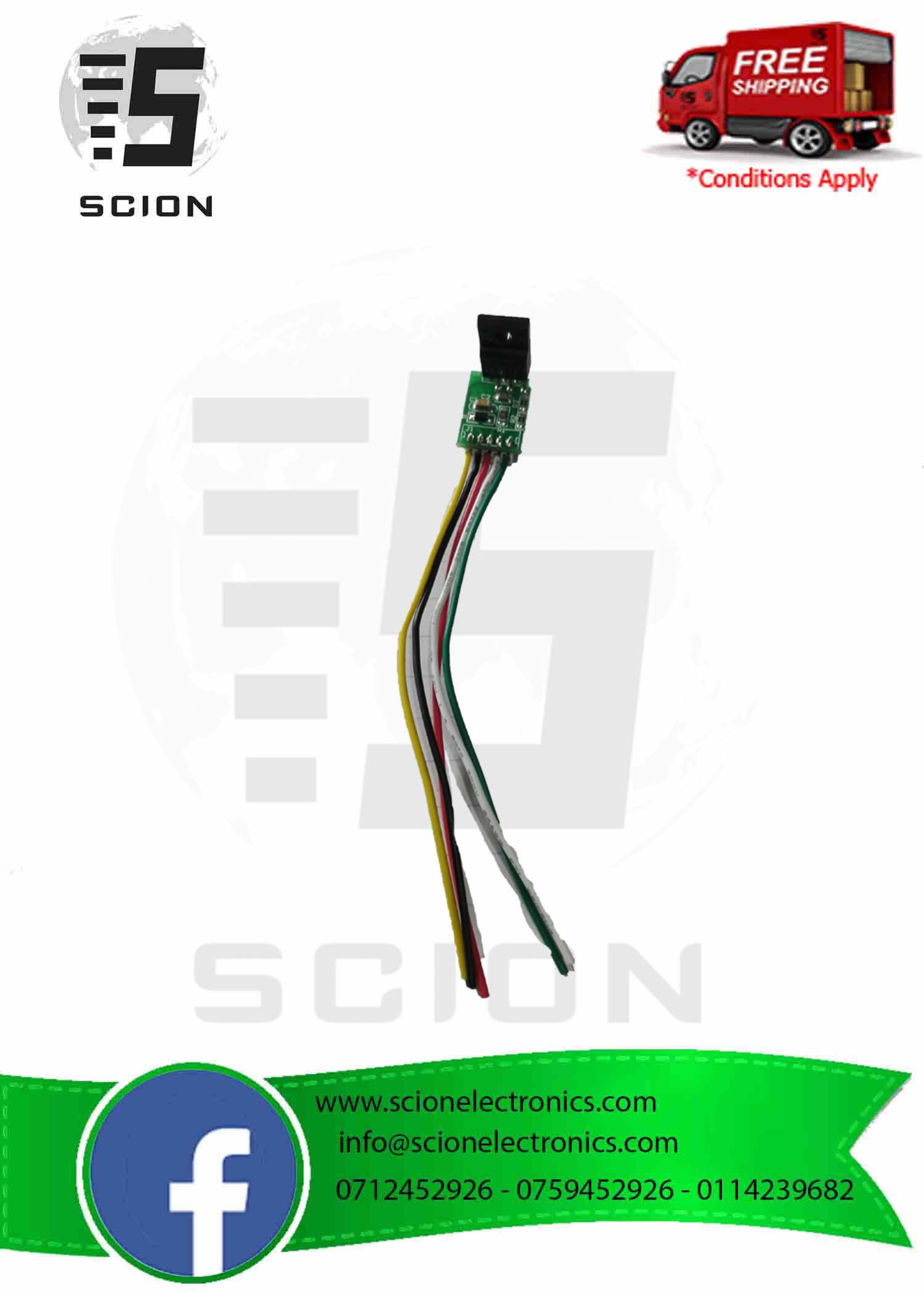
LCD TV Power Module 5 Wire DM0565R
රු340.00
Moratuwa: 0 in stock
Out of stock
Description
Uses
Solve the problem of 15-21 inch LCD monitor power failure maintenance. Damage to the LCD power strip occupies a large percentage. Among them, power drive chips, high-power power switch tubes, sampling resistors, etc. are the most common. Due to the variety of models and varieties, they often cannot be repaired because they do not have the same spare parts.
The general power supply module of the liquid crystal display has been developed in response to the needs of customers. The module has the advantages of simple wiring, convenient installation, time saving and improved maintenance success rate.
Pin definition
1 foot Yellow line: DRAIN, power control terminal, connected to the original high power MOS power supply tube D pole. Generally the middle leg of the power switch tube
2 feet Black line or powder line: GND, module ground line 300V, the negative pole of the capacitor, can be on the same line. Directly connected to the negative pole of the large filter capacitor
3 feet Red line: VCC, module power supply end, connected to the positive side of the rectified capacitor after the feedback winding end, continuous power supply, voltage between 12-18V.
4 feet White line: FB, voltage feedback, connected to the photocoupler 4 pin, please confirm that the optocoupler 3 pin is connected to the hot ground. If it is not hot, short the optocoupler to the hot ground and disconnect the 4-pin peripheral circuit.
5 feet Green line: start Start pin, connect positive electrode of +300V capacitor
Customers must be optimistic about the specific connection method and then carry out the modification, do not blindly connect.
How to use
1. Remove the power chip (usually 8 feet) on the original board, and the switch tube (mos tube)
2. Check the capacitance of 300V, and there is no drum kit on the appearance of the capacitor on the load side. If there is any problem, replace it first.
3. Check if there is any short circuit at the load end, ad board, high voltage board, etc.
4. Connect the corresponding line of the module and check carefully that there is no error. If it is wrong, it will cause the module to burst.
5. Install in the original radiator position, pay attention to insulation, do not short circuit
6. Power on, measure voltage is not output, if there is no output, check the reason
Can replace the following inline and patch:
1. 203D6.230D6 NCP1203D60R2G 203X6
2. LD7552BPS LD7552BN LD7575PS LD7576GS LD7522 LD7523
3. OB2268.OB2269
4. 3842.3843.3844.3845
5. EA1530.EA1532 TEA1507 TEA1522
6. DAP8A DAP08
7. 1200AP40 1200AP60 1200AP100 1203P60 1203P100
8. FAN7601.FAN7530 FA5511 FAN6961 FA5500
9. L6562D.DM0365R 5H0165R DM0365R 0665 0265
10. NCP1271 NCP1270 NCP1653
11. 2AS01.2BS01 FSQ100
12. SG6961 SG6841 SG6842 SG5841
Note
1. Before using this module, please check whether there is a short circuit at the cold end. If there is a short circuit, please repair it first. If the capacitor drum is packaged, please replace it first. The short circuit of the high voltage package circuit is also disconnected first. Before the module is removed, remove it. The power chip and mos tube of the original module, at this time, the electrode in the middle of the original switch tube has a voltage of about 300V to the ground voltage.
2. If the 3 pins of the optocoupler are not connected to the ground, please connect the 3 pins to the ground, and at the same time, disconnect the circuit around the 4 pins and connect the white wire to the 4 pin position.
Troubleshooting
1. No output: wiring error, can not be connected wrongly or missed, so that only the chip can be burned, the load terminal is determined to be short-circuited, and the optocoupler has no problem.
2. The optocoupler part is not properly controlled. The optocoupler 1 is not grounded. The 2 pin is connected to the vcc part through a resistor.
3. The heat is severe. If the tube is used for less than 10 minutes, the cause of the load is too heavy. Check the diode and capacitor damage on the hot side of the transformer.
Voltage is unstable, jump: the load is too light or too heavy, the voltage continues to jump is the load is too light, the snoring is too heavy, generally there is no load connection may cause a slight voltage jump, mainly due to different transformer design, can Try to connect the load, or connect a 100 ohm resistor at 5V to test.
Compatibility questions, a variety of power boards have been tested at present, a wide variety, incompatible is inevitable.
Additional information
| Weight | 0.005 kg |
|---|
You must be logged in to post a review.


Reviews
There are no reviews yet.